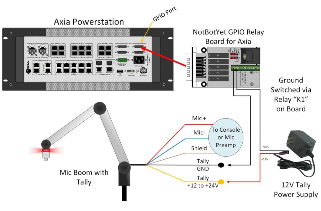
The NotaBotYet GPIO Relay Board for Axia can be used to control tally lights on popular mic arms. Most of these types of mic arms have a ring of multiple LEDS that are used to indicate which mic is live on the air. These LEDs at 12 volts typically draw 30-40 milliamps of current, and possibly more at 24 volts. This is more current than a GPIO port on an Axia device is rated to handle. Many engineers out there have resorted to creating some sort of perf-board circuit with transistors or relays to control these tally lights. Some have even gone with quick and dirty “transistor directly in the euroblock” method of wiring.
The problem is that none of these methods are easy or quick to install. With the GPIO Relay Board, NotaBotYet has already done the heavy lifting for you to make your installation fast and easy. Typically, when using this board, the most time will be spent stripping wires on the mic arm to find the correct colors rather than making connections to the GPIO port itself.
The diagram above demonstrates how it all goes together. All that is required to make the proper connections are: the mic arm with tally light built in, a GPIO port on any given Axia device, a 12v to 24v power supply to power the tally light itself, some wire (unless this is being installed in an alternate Tesla universe), and the NotaBotYet GPIO Relay Board for Axia. The normally open relay contacts will activate upon the GPIO port bit closing to ground, thereby completing the circuit to the tally light, and remaining completely electrically isolated from the other relays on the bord as well as the GPIO port itself.
Using Axia’s Pathfinder software will allow advanced control of most GPIO ports in an Axia Livewire network with a granularity down the level of each bit on a particular port. Using Pathfinder in conjunction with the Relay Board can allow one Relay Board to control up to five tally lights simultaneously.

