The Old Slow Way!
The Axia Film Cap Button panel is a useful and versatile tool in the Axia product line, however it can require an extensive amount of soldering of custom length 15-pin D-Dub cables to install. Watching engineers spend hours soldering wires to the D-Sub connectors was the inspiration for the GPIO Breakout Board for Axia (not to mention those little screws that have to be sandwiched “just right” to get the hood to go together correctly). When using NotaBotYet GPIO Breakouts and some inexpensive Cat-5 patch cables, a 5, 10, or 15 button panel can be hooked up before a soldering iron is even hot enough to begin soldering. If time is truly money (and it is) then the savings on a small or large project can be clearly realized.
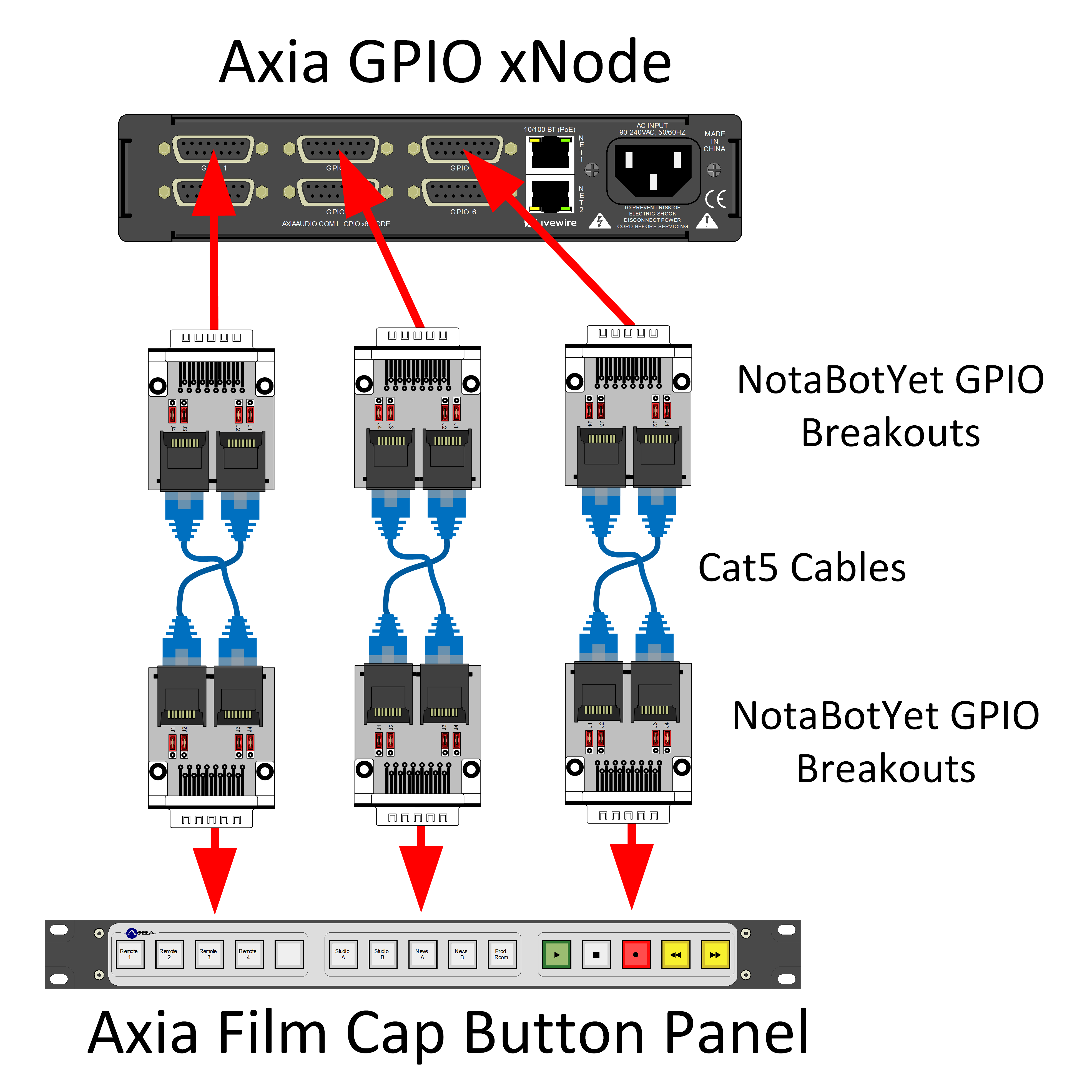
In the diagram above, a 15 button panel is shown with the hookups to matching ports on an Axia GPIO xNode. If this were a 5 or 10 button panel, then less ports would be required.
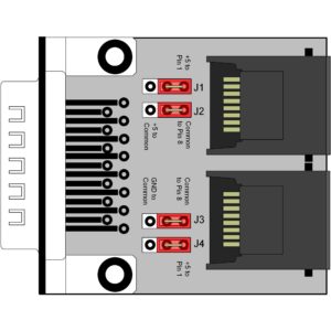
Jumpers set toward the RJ-45 Connectors
The above scenario requires positioning the jumpers of the Breakout Board toward the RJ-45 connectors as opposed to toward the 15-pin D-Sub connector. This allows the special GPIO pins such as common and +5V to pass through the RJ-45 connectors. A Breakout board is placed on the 15 pin port on the Axia GPIO port(s) as well as the 15 pin connector(s) on the back of the button panel. Because the button panel is designed to be wired pin for pin in a straight-thru fashion on the 15 pin connector, the RJ-45 IN on the GPIO port is connected with a cat-5 patch cable to the RJ-45 IN on the button panel. Likewise, the OUT connectors on each breakout board are also connected to each other using a Cat-5 patch cable as well. This has the effect of passing the required pins like-for-like through the Cat-5 cables. No soldering required!