The NotaBotYet Tally Helper 100 was designed to control tally lights on popular mic arms such as Yellowtec Mika products and others. Most of these types of mic arms have a ring of multiple LEDS that are used to indicate which mic is live on the air. These LEDs at 12 volts typically draw 30-40 milliamps of current, and possibly more at 24 volts. This is more current than a GPIO port on an Axia device is rated to handle. Many engineers out there have resorted to creating some sort of perf-board circuit with transistors or relays to control these tally lights. Some have even gone with quick and dirty “transistor directly in the euroblock” method of wiring. The problem is that none of these methods are easy or quick to install.
What’s more is the fact that newer mic arms with built in tally lights now support dual colors, typically red and white. Some installers like to use one color for “on-air” indications and the other color for “Recording,” or “phone ringing,” or some other useful annunciation. However, to use one color or the other, the polarity of the supply voltage must be reversed, making a control circuit a lot more involved and complex.
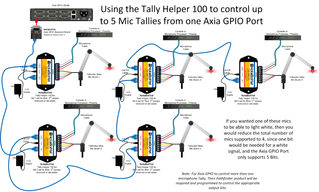
Figure 1. Typical wiring Diagram for 5 Mic Arm Tallies using Tally Helper 100’s
The problem is that none of these methods are easy or quick to install. The Tally Helper 100 solves several problems for the installer. One Axia GPIO port can be used to control up to 5 mics arm tallies. If dual colors are required, each color takes an additional GPIO bit. For instance, 5 red tallies can be controlled with one port, but if one tally needs red and white, then one port can only control 4 tallies. If two tallies are required to be dual color, then only three tallies can be controlled. Give the odd number of bits in an Axia GPIO port, there is no way to control three mic arm tallies with dual color as it would require six GPIO bits.
The diagram above demonstrates how it all goes together. A NotaBotYet GPIO Breakout for Axia is connected to an Axia GPIO xNode and then a standard cat-5 cable connects the output of that board to the Tally Helper 100. Control then loops out of one Tally Helper to the next one in the chain. The power supply for each Tally Helper 500 powers the unit and also provides power for the mic tally.
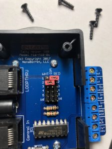
Jumpers select which bits will light which color on a given Tally Helper 100.
The cover must be removed from the Tally Helper 500 to use the jumper selectors to program the device to respond to the appropriate bits. There are two jumpers in each device selecting which input bit will activate the red output and which will activate the white output. By default the device comes pre-programmed to select red on input 1 and white on input 2. If only red or white is desired, the other corresponding jumper may be left off so the device will not respond to other bits.
Using Axia’s Pathfinder software will allow advanced control of most GPIO ports in an Axia Livewire network with a granularity down the level of each bit on a particular port. Using Pathfinder in conjunction with the Relay Board can allow one Relay Board to control up to five tally lights simultaneously.
One may also note from the drawing that the Tally Helper 100 has a mic loop through. This allows the installer to install a mic arm such as a “Mika On Air Mic Arm” or the “Mika On-Air Mic Arm TV” without soldering on any XLR connectors to the booms built in wiring. Simply tin the ends and connect directly to the 5mm screw terminals. Then using any quality 3 wire microphone cable, make the connections to the output terminals and terminate to a mic preamp or console mic input. This eliminates the need for 5 pin XLR’s and associated hassles, while still allowing the user to make a fast swap out of a mic arm if it needs replacement. Simply loosen 5 screws on a screw terminal.