 For a facility designer and/or installer, it has always been an enigma how best to deal with the 5 wires coming out of a Yellowtec Mika microphone boom with a built in tally light. Various methods may include:
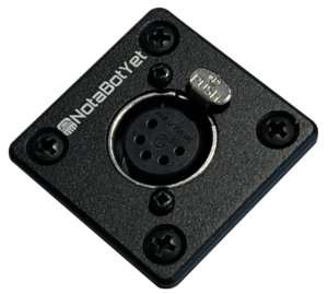
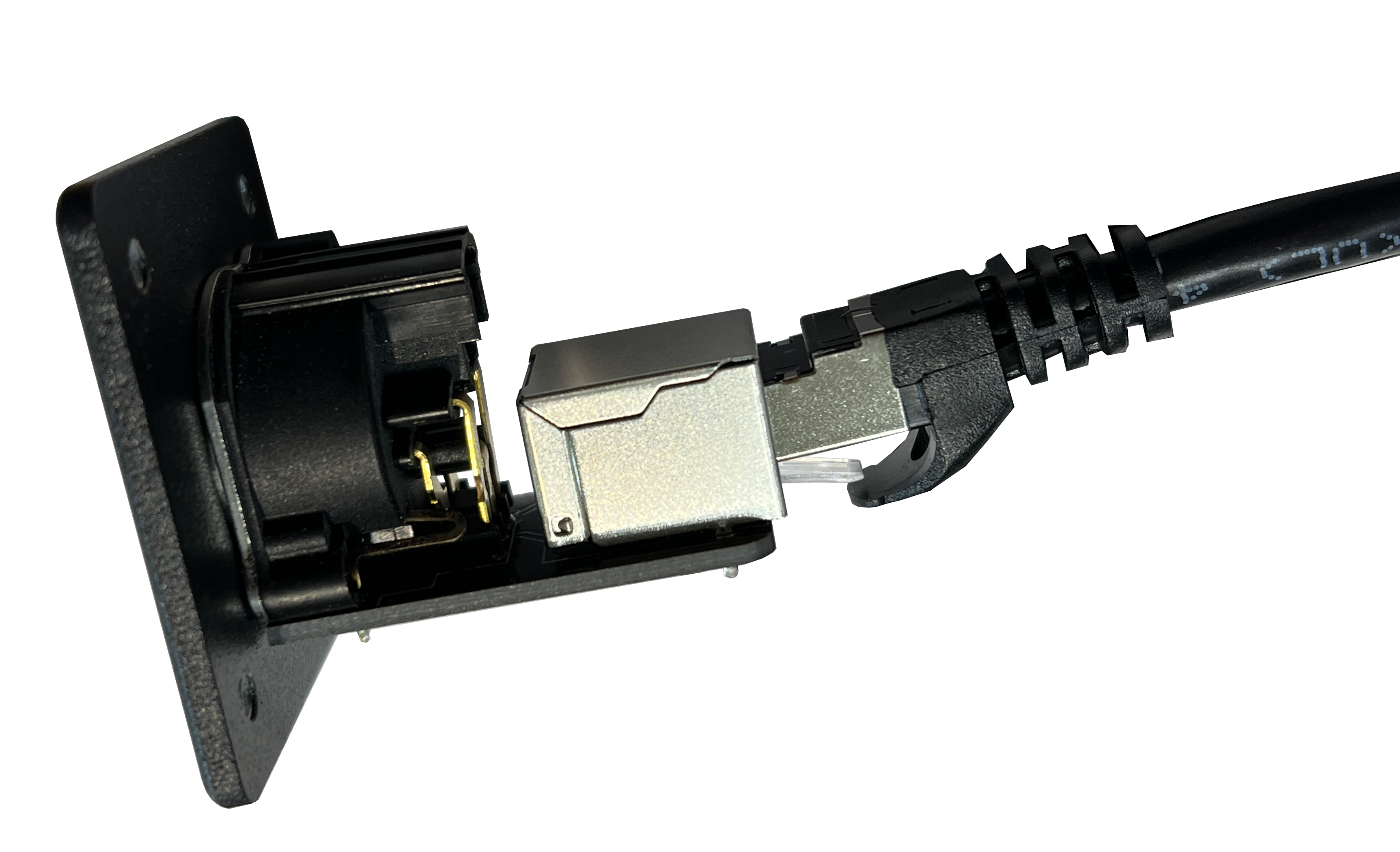
- Termination using 5 pin XLR connectors
- Terminating on a 3 pin XLR and looping the 2 tally control wired back out the rear of the connector
- Hard Wiring into a Euro Block Terminal Strip
- Scotch tape and bubble gum
All of these methods take a lot of time (Except the Scotch tape method, that one goes pretty fast) and none of these are super versatile. While the Mika arms can be ordered with a 5-Pin XLR conveniently preinstalled, connecting them without the Tally Helper 150 would require significant time and effort. Who wants to wire up a mating 5-Pin XLR, build a custom circuit on a perfboard and split out all those wires. Of course, it never looks as neat as you want. Lucky for you we did all the hard work for you! The Tally Helper 150 makes short work of connecting Yellowtec Mic booms.
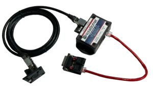
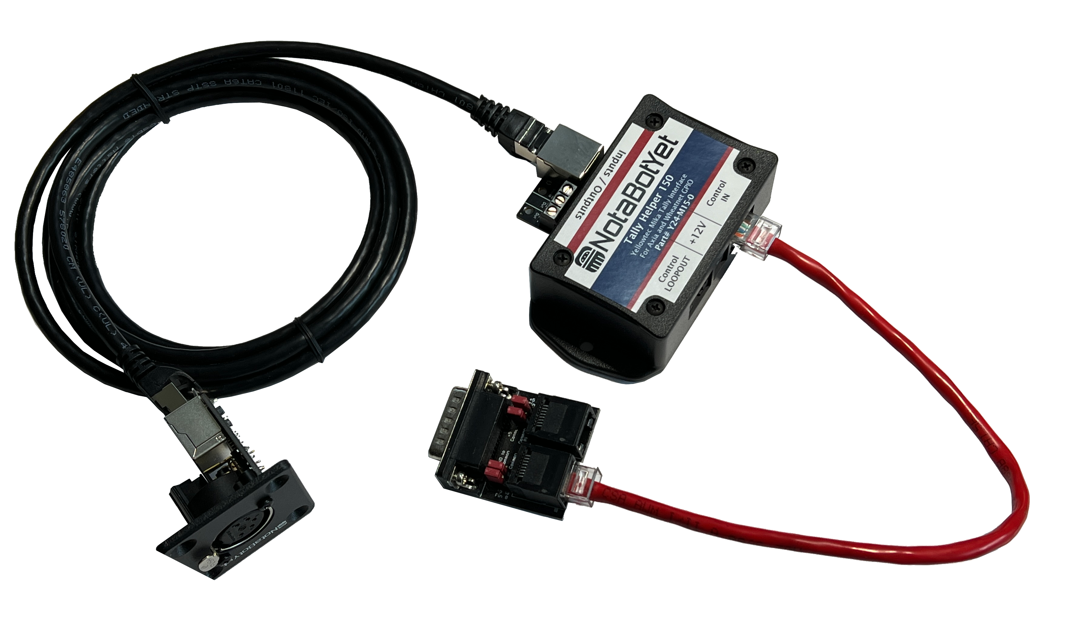
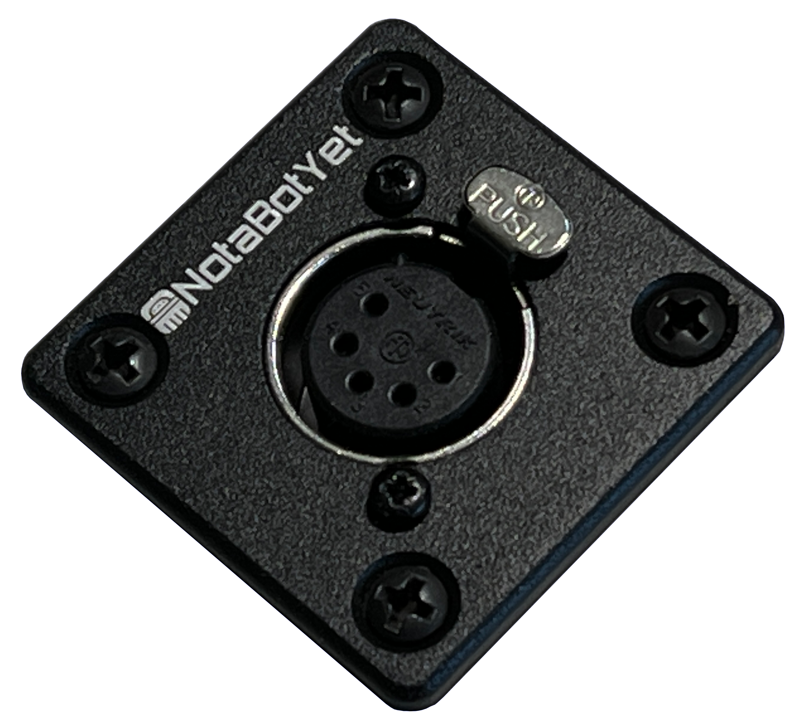
Tally Helper 150 Shown with Included 5-Pin XLR and Shielded Cat5 Cable. (Axia Adapter not Included)
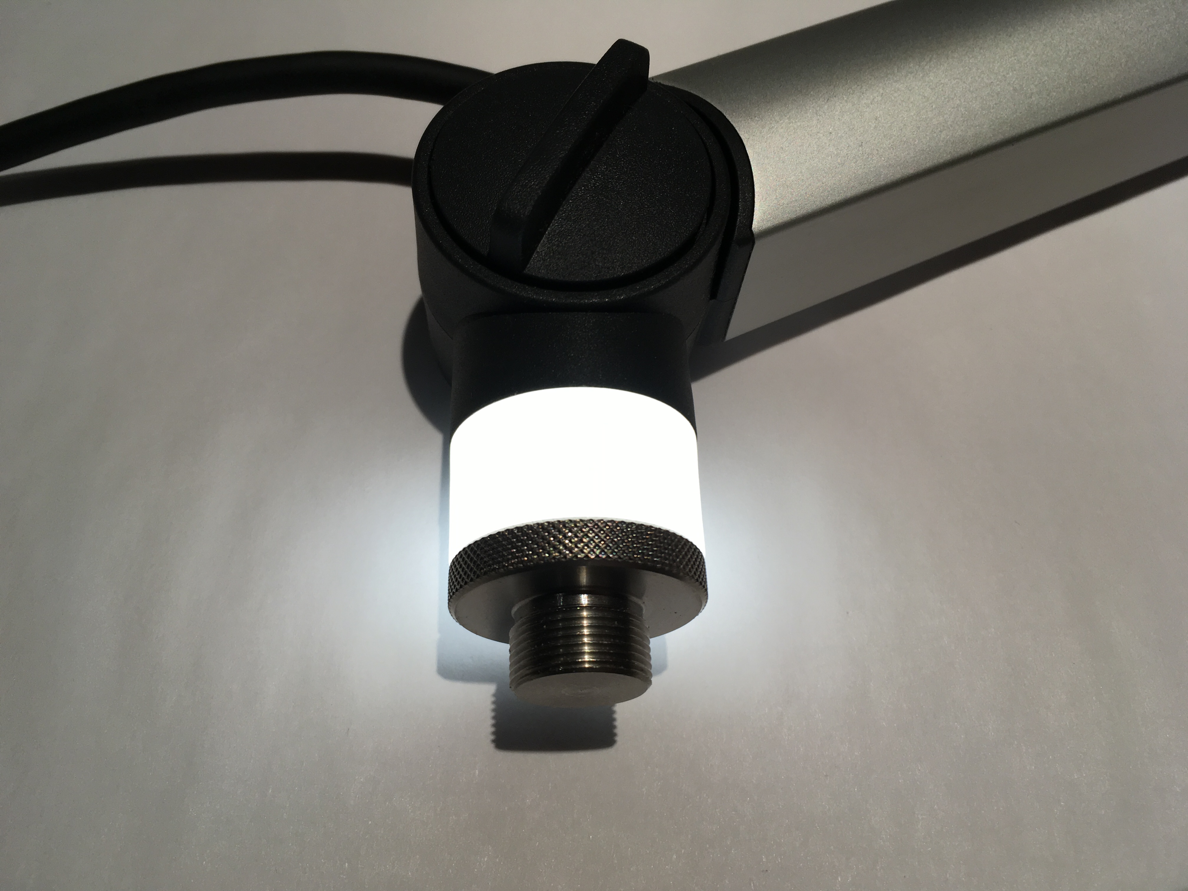
A feature of the Mic Booms from Yellowtec is they have both red and white tally indicators, however when installing using traditional wiring methods, you must choose which color will be permanent in your installation. Once again, we have you covered! Both the red and white indicator lights can be controlled simply by choosing the input control bits of the interface. An included power supply provides power for the tally lights as well as the device.
With our interfaces, driving the tallies in an entire studio full of Mika booms can be achieved faster than most engineers can heat up the soldering iron. While the Tally Helper 150 does not solve all of life’s problems, when installing Mika mic booms, it comes pretty darn close! Imagine having a nice clean counter-mounted XLR connector just waiting for a Mika 5-Pin XLR to be securely plugged into it. Imagine a shielded RJ-45 cable making a quick and easy conenction to the control box. Imagine convenient screw terminals for the Mic audio to be peeled off toward your favorite mic preamp. Imagine having a power supply that plugs into the device and provide a solid 12 volts of regulated power. Imagine an easy RJ-45 connector waiting to be plugged into an Axia GPIO port or Wheatnet Logic port or any standard GPIO type output that provides a closure to ground to activate. Imagine being able to decide which GPIO input bit will trigger the red tally and which will trigger the white tally. That is quite an imagination, but actually it is all real and ready to help on your next build.
The Tally Helper 150 has the following features:
- Counter Mounted 5Pin Female XLR to receive the Mike Audio and Tally signals.
- Phoenix-type screw terminal strip for the ground isolated loop-thru connection to mic preamp.
- Included 12V regulated switching power supply.
- RJ-45 input connector with pinouts matching our Axia GPIO Breakout Board (Part# A15-B01-2) or Wheatnet IP logic ports.
- Active low inputs mean installers can any standard GPIO source (using open collector type closures to ground or relay closures to ground) to control the device
- Programmable jumpers allowing installer to determine which GPIO bit will trigger the Red tally and which bit will trigger White tally. this means you can daisy chain units off one GPIO port!
- Small device can be mounted discreetly under the counter in a convenient location
Instruction Sheet
|
Part # Y24-M15-0 | ||
|
 |
 |
|
 |
 |
|
|